Self-Sensing-Spindle

In the field of magnetic bearing technology, the self-sensing spindle is used to investigate in position estimation methods for self-sensing magnetic bearings. The focus is on the general applicability of the developed estimation method for different designs and bearing variants.

CAD model of the spindle

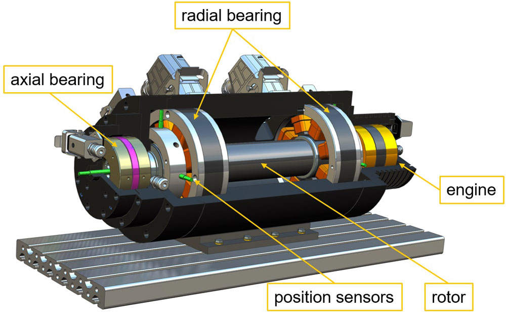
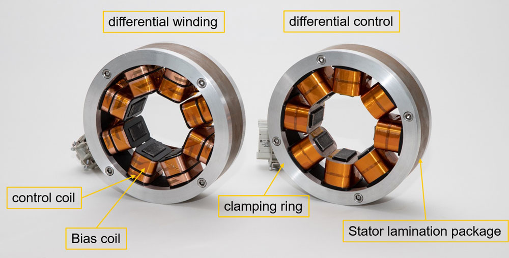
The test bench consists of the mechanical components of the spindle as well as the power electronics in the form of the output stage and the motor converter. The rotor of the test rig is made of tempered steel. The sensor target and the lamination packs of the magnetic bearings are shrunk onto it and thus form a unit. The stator consists of the magnetic bearings, the position sensors and the drive unit. Due to the modular design, different bearing variants in the form of differential control and differential winding as well as different magnetic materials can be tested in the test rig for their suitability for self-sensing.

Design of the radial bearings in differential winding and differential control

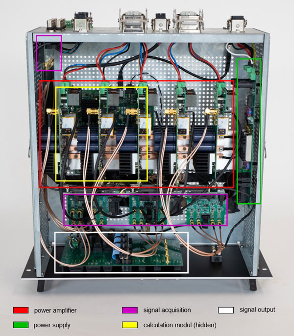
The magnetic bearings are controlled by pulse width modulation. For this purpose the power electronics has 10 power amplifiers, each of which can provide an output voltage of 48 V and an output current up to 12 A. The calculation of the pulse width is done by a FPGA. For self-sensing, a transformer is additionally installed at the power amplifiers, via which the current gradient in the magnetic bearing coils, which is necessary for the position estimation, is converted into a voltage signal. This also allows operation without position sensors. To determine the quality of the estimated position signal, position sensors are nevertheless installed. With these sensors comparisons between conventional position detection and self sensing operation can be made. The drive unit is a permanently excited synchronous motor with which up to 16,000 rpm can be reached for short periods and 10,000 rpm for long periods.

Design of the magnetic bearing amplifier

Due to the modular design of the spindle as well as the specially developed magnetic bearing amplifier, investigations on different bearing variants and materials can be carried out. The aim is to improve the quality of the estimation signal and to determine factors influencing the estimation signal by using different materials. In addition to the mechanical components, the estimation procedure can be investigated and parameters can be adjusted to improve the estimation signal. In addition, new control approaches for both conventional bearings and self-sensing bearings can be tested.

  • Development of self-sensing magnetic bearings, KoREV
  • Improving the accuracy of the position, KoREV II
Spindle
rotor material tempered steel
diameter 65 mm
length 408 mm
radial bearing materials M270-35A
NO10
NO20
bearing variants differential winding
differential control
max. force 150 N
max. current 6 A
air gap 0,5 mm
axial bearing bearing variants double-sided reluctance bearing
materials tempered steel
SMC (soft-magnetic-composite)
max. force 160 N
max. current 6 A
air gap o,5 mm
engine variant permanent excited synchronous motor
manufacturer ATE
type DC 90/20/4
max. torque 0,3 Nm
max. rotational speed 16.000 rpm
inverter Sieb & Meyer SD2S
magnetic bearing amplifier
FPGA manufacturer National Instruments
type NI USB-7856R OEM
clock frequency 160 MHz
analog in-/outputs 8
digital in-/outputs 48
signal acquisition analog digital converter 12
resolution 18 bit
max. sampling frequency 1 MHz
power amplifier number of modules 5
DC link Voltage 18 V – 72 V
max. output voltage 12 A
number of power amplifiers per module 2
switching frequency 20 kHz
Systemsoftware LabVIEW
position sensor manufacturer Balluf
type BAW0052
measuring principle inductive
measuring range 0,5 mm – 2 mm
output voltage 0 V – 10 V
max. temperature 60 °C
current sensor manufacturer SENSITEC
type CMS3005
measuring principle Anisotropic magnetoresistive effect
measuring range -20 A – 20 A
bandwith 2 MHz
output voltage -10 V – 10 V
temperature range -40 °C – 105 °C
singal transformer turns primary coil 24
turns secundary coil 36
inductivity primary coil 80 μH
Relative inductance change of the primary coil 0,5%
core type and material PQ32/20 aus N87
air gap in the core center 1,4 mm