Kinetic Storages

As of today, kinetic energy storages are only used in niche applications. There is a need for research in terms of the complexity of the systems, the resulting high investment costs and energy losses. We are working to transform the technological potential into a broad economic application.

Kinetic storage
Kinetic storage

In kinetic energy storage systems, electrical energy is converted by an electric motor into kinetic energy of the rotation of a flywheel mass. The system is subject to low calendrical and cyclical aging, which is one of the key advantages of this storage technology.

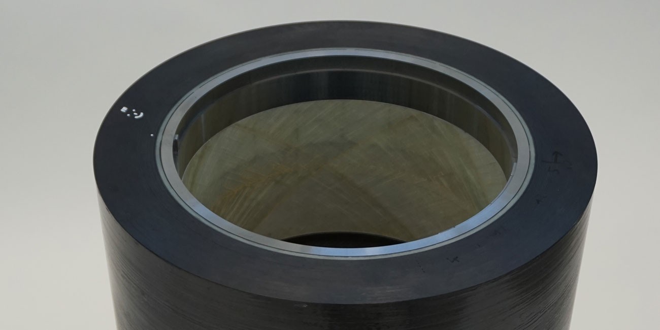
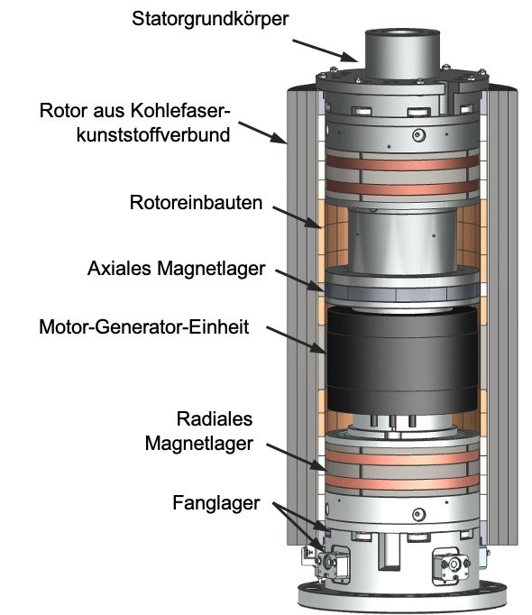
The energy content of the system is linearly dependent on the inertia of the flywheel mass and quadratically on the rotational frequency. Therefore, the energy content can be efficiently increased via high speeds and flywheels with a high inertia. The use of contact-free magnetic bearings and the operation under vacuum conditions enable high maximum speeds with low losses. At the same time the systems are wear-free. Speed limitations result from the high centrifugal load and the resulting radial enlargement of the rotor. By using flywheels made of fiber-reinforced-plastic composites, it is possible to increase the utilization of the flywheel mass and to store larger amounts of energy in a single system.

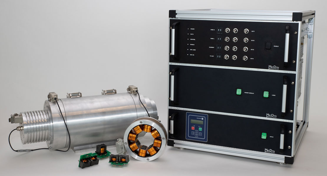
The aim of our research is to improve the cost-effectiveness of these systems by further increasing the energy and power density while reducing the energy losses at the same time. Highly integrated concepts, such as the design as an outer rotor, are addressed and tested using full-scale demonstrators. We strive for innovations on both component and system level. That is why, in addition to the system demonstrators, dedicated component test benches for planetary back-up bearing concepts, fatigue strength testing of carbon fiber rotors and active magnetic bearings were developed.

Orbit from simulation

In order to reduce the losses of the kinetic energy storage systems, magnetic bearings are usually to suspend the rotor. Since a failure or overload of the magnetic bearings can lead to severe damage to the system, an additional mechanical fallback system, the so-called backup-bearing, is introduced into the system. The back-up bearing must prevent an unintentional rotor-stator contact and ensure a safe shutdown of the system.

Kinetic energy storage systems in outer rotor design present a particular challenge for back-up bearing systems, as they can reach very large surface speeds at the point of contact and as they have a high inertia. Since conventional bearings are not suitable for the task, a special planetary back-up bearing system is used, in which several rollers are distributed over the circumference of the stator. In order to further develop this concept, both the multibody simulation environment ANEAS (Analysis of Nonlinear Active Magnetic Bearing Systems) to predict non-linear behavior in the event of a rotor drop-down, as well as a specially developed back-up bearing test bench, which enables safe and cost-effective testing of drop-downs under realistic conditions.

Planetary back-up bearings are investigated in the project KoREV-SMS II .

Calculated stress distribution in a sample

When charging and discharging the kinetic energy storage, the flywheel is accelerated and decelerated. As a result, the mechanical load on the flywheel varies, which can lead to fatigue failure of the material in the long run. Despite the high fatigue strength of the material , it is of great importance for the design of the rotors to be able to determine the exact strength limit in order to maximize the stored energy and to dimension the containment.

Standardized material testing procedures can be used for this purpose. These, however, have the disadvantage that they do not allow an exact quantification of the strength of the rotor because they neglect other influencing factors, such as the superimposition of various stress components andthe high material thickness. For this reason, a centrifugal test rig has been developed at the IMS, with which the cycle stability of thick-walled hollow cylinders made of fiber-reinforced plastic composites can betested. To reduce costs and test duration, the test is carried out using a scaled, magnetically levitated tests bench. In time-lapse, the life cycle of a kinetic energy storage is completed within two to three months. Furthermore, the test bench is used for destructive testing of the rotors, whereby the bursting behavior is of particular interest.

The fatigue strength of fiber composite rotors is investigated in the project KoREV-SMS II .

Power stage and spindle

A very relevant component in kinetic energy storage systems is the active magnetic bearing, which is specially tailored for this application. In the context of the outer rotor design, new challenges arise in the field of control, position measurement and the premagnetization of the bearings.

In the field of control, the influence of the speed-dependent rotor behavior plays a central role. The high rotational speed of the systems leads to a radial enlargement of the rotor leading to speed-dependent properties of the magnetic bearing. This influences the rotor dynamics and thus the operating range of the systems. At the same time, the unbalance of the used rotors is large due to the large rotor diameter and manufacturing tolerances of the carbon fiber rotors leading to speed-dependent gyroscopic forces that must be compensated by the magnetic bearing. The resulting control activity of the bearing reduces the efficiency of the system. Compensation of these speed-dependent influences by appropriate control approaches is currently being investigated at the IMS.

Self-sensing magnetic bearings are another field of research. A magnetic bearing basically consists of an actuator (electromagnet), a sensor for position measurement, a controller and the rotor. The requirements for position measurement are high resolutions, high bandwidths and a suitable measuring range, resulting in high acquisition costs for these components. Self-sensing approaches, where the bearing itself is used as the sensor, try to eliminate these costs. At the same time, the probability of failure decreases as the number of system components is reduced. At the IMS, a estimation method suitable for practical application was developed and implemented, which determines the position from the magnetic bearing properties during control. The solution is highly cost-efficient because it uses standard components that are already installed in industrial magnetic bearing power electronics.

The use of permanent magnetic premagnetization offers great potential of increasing the efficiency of the magnetic bearings. The premagnetization of the bearings is necessary to generate a high force dynamic. State of the art is the premagnetization via dedicated coils. Due to the high constant current through this coil, comparably high losses are generated. That is why, concepts for permanent magnetic premagnetization are investigated at the IMS. Both analytical and numerical models show that a permanent magnetic premagnetization enables a loss reduction of up to 80% in the magnetic bearings, which significantly increases the energy efficiency of the overall system.

New magnetic bearing concepts are investigated in the project KoREV-SMS II .