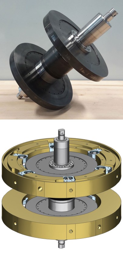
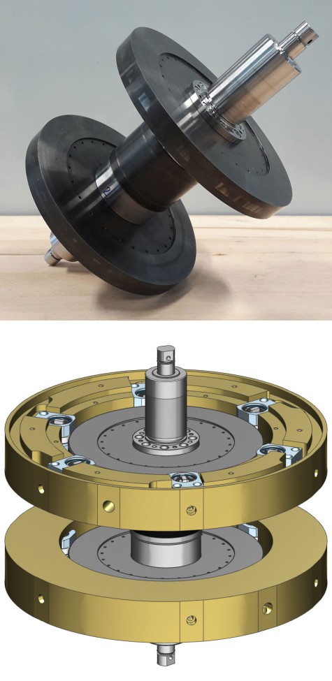
Touch-Down Bearing Test Rig

The purpose of the touch-down bearing test rig is to generate drop-downs of the fast-rotating rotor into the touch-down bearings by a deliberate failure of the magnetic bearings. The focus here is on the use of conventional as well as planetary touch-down bearing designs. The drop-down behaviour and the durability of the touch-down bearings are investigated.

The test rig offers an optimal environment to test the touch-down bearings in different designs, which are highly stressed in case of a rotor drop-down. The test rig is designed as inner rotor, but the rotor dynamic properties are similar to the flywheels in external rotor design developed at the IMS. The magnetic bearing consists of two radial and one axial active magnetic bearing, controlled by a magnetic bearing amplifier. The rotor is accelerated and decelerated by a permanent magnetic synchronous machine. By the integrated sensors the speeds and temperatures of the touch-down bearings are recorded. In addition, the contact forces between the rotor and the touch-down bearing unit is measured to obtain information about friction and wear. In this way, the economic efficiency and availability of these mechatronic systems can be increased in the future. The test rig concept is characterized by a robust and modular design with active magnetic bearings.

By drop-downs into different touch-down bearing configurations, it is possible to determine specific factors influencing the rotor behaviour in connection with the service life of the touch-down bearings. The goal is the validation of the simulation environment ANEAS in order to design touch-down bearings in different configurations for new systems.

KoREV-SMS2

  • Influence of the number of bearing elements of the planetary touch-down bearing on drop-down behaviour
  • Influence of different damping elements on the drop-down behaviour
  • Influence of asymmetries in the geometry and in the damping properties
  • Influence of gaps and steps in the touch-down bearing raceway as they occur in the flywheels build at the IMS
  • Determination of characteristic values for the service life of touch-down bearings
Rotor speed Max. 21000 rpm
Rotor diameter, touch-down bearing plane 220 mm
DN-Number 4600000
1. bending frequency, rotor 1469 Hz
Rotor mass 18 kg
Inertia ration Jp/Ja 0,58
Drive power 25 kW
Operating pressure 10-3 bis 10-5 mbar
Touch-down bearing gap, planetary 150-300 µm
Amplifier Mecatronix AG Control frequency 8 kHz
Switching frequency 20 kHz
Eight independent amplifier channels
Drive Permanent magnetic synchronous machine from ATE
Inverter from Sieb & Meyer
Data acquisition with LabView Temperature with 100 Hz,
force with 8 kHz
speed 8 kHz
Position with 8 kHz
Eddy current (Eddylab T2) Radial rotor position
Inductive sensor (Balluf BAW0033) axial rotor position
Hall effect sensor (Allegro ATS667LSG) Rotation frequency of the rotor
Rotation frequency of the touch-down bearing units
Temperature sensor (PT100) Temperature des of the touch-down bearing units
Temperature sensor (KTY84-130) Temperature of the drive windings
Infrared-Thermometer/Pyrometer (optris CT 3ML) Surface temperature of the touch-down bearing raceways
Piezoelectric force sensor (PCB 211B) Contact force between rotor and touch-down bearing
Pressure sensor (Pfeiffer Vacuum Compact Full Range Gauge) Pressure in the containment
Strain gauge Normal and tangential force of the touch down bearing